
NASA Lunar Surface Operations
Lunar sampling device to be used for the collection of loose rocks from the surface of the Moon on Artemis missions.
The purpose of the dust-tolerant lunar sample collection device is to allow a NASA crew member to pick up float samples from the lunar surface. The device constraints included lunar dust tolerance, the ability to pick up float samples ranging 0.5” to 3” in diameter, and being operable while wearing an EVA suit, which limits movement of the astronauts. Additionally, the device had to be manually operated with a length of 30" to 35” and a max weight of 3 pounds.
Approach to Solution
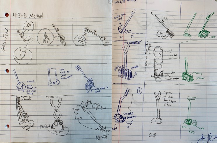 The initial brainstorming phase consisted of sketching any concepts that would solve the problem statement provided by NASA. Through
this process over 40 designs were proposed. This number would be trimmed down with the use of a weighted decision matrix where
criteria that was believed to be more important were weighted higher than those of lesser importance. For instance, safety would be rated
at a full 10 points since it was of utmost importance while manufacturability was rated lower at a 6 due the use of an integral design
approach.
The initial brainstorming phase consisted of sketching any concepts that would solve the problem statement provided by NASA. Through
this process over 40 designs were proposed. This number would be trimmed down with the use of a weighted decision matrix where
criteria that was believed to be more important were weighted higher than those of lesser importance. For instance, safety would be rated
at a full 10 points since it was of utmost importance while manufacturability was rated lower at a 6 due the use of an integral design
approach.
Design Solution
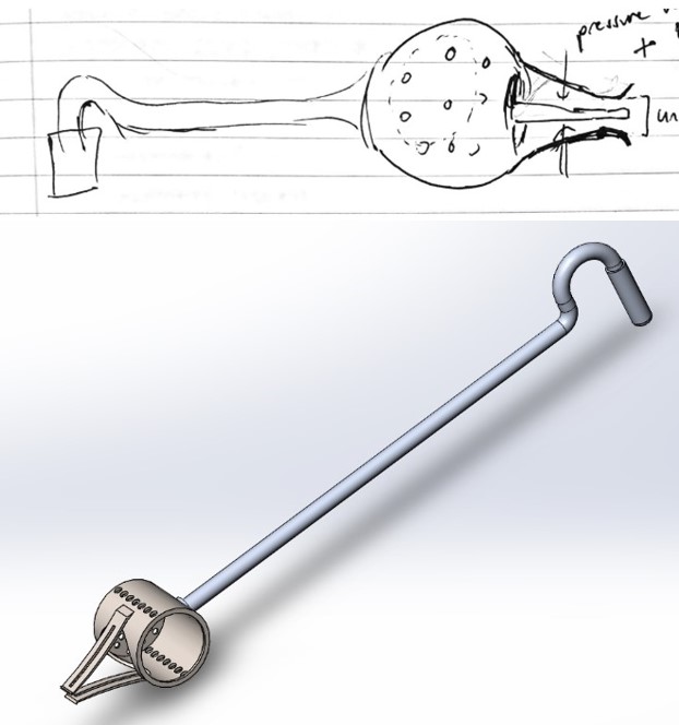
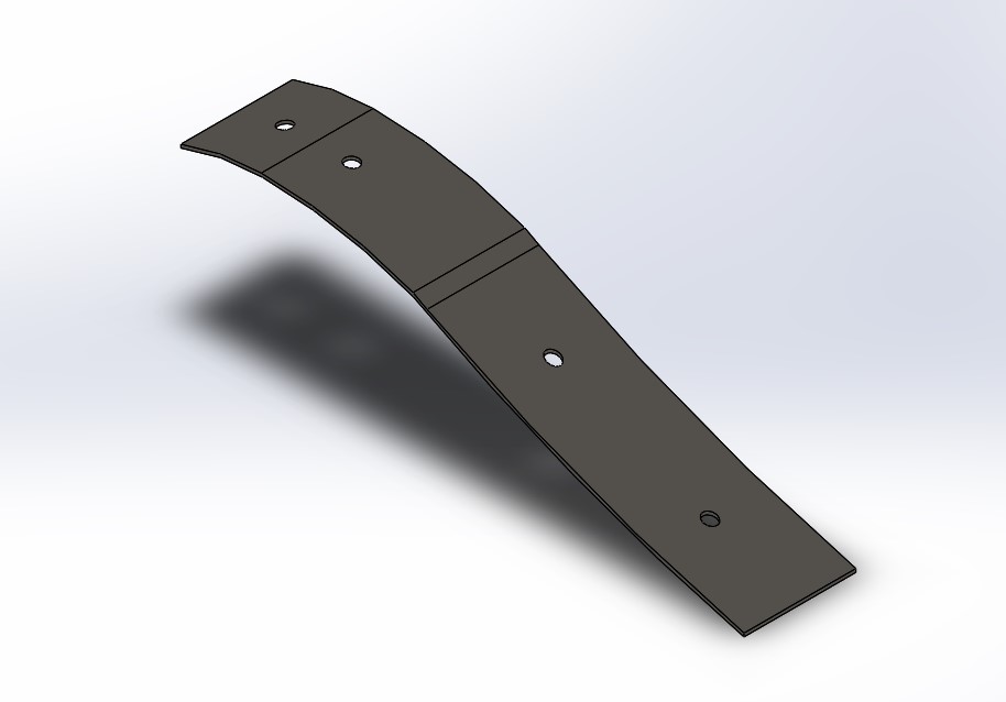
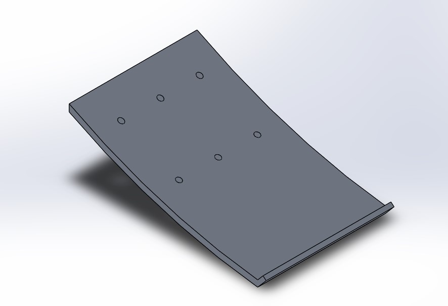
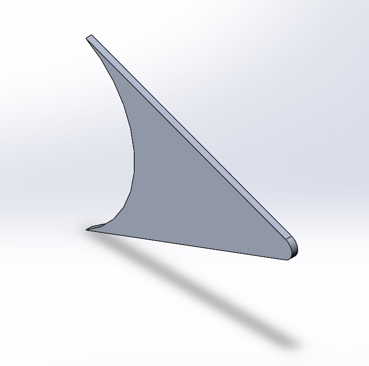
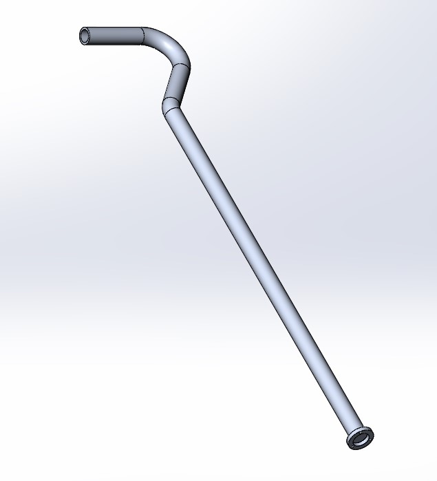
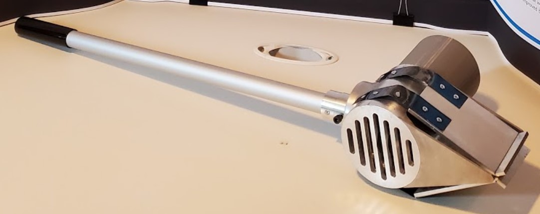
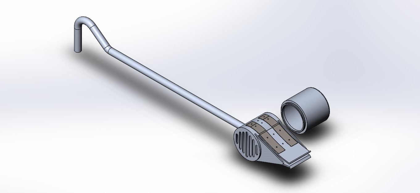 The final design incorporates a simple grabbing mechanism with a detachable cup for storage. The design’s key feature
is the spring steel mechanism which is actuated when the user applies a force at the top of the handle.
The end plates of the device deflect when the force is applied downwards by the user onto the sample. This mechanism
reduces the amount of dust sifted around due to the decreased surface area in contact with the ground compared to
a design like a standard shovel. That feature allowed this design to be rated highly in the decision matrix as it received
full points on safety. All in all, the design's ease of use and safety features are what made this solution the most
optimal for this project.
The final design incorporates a simple grabbing mechanism with a detachable cup for storage. The design’s key feature
is the spring steel mechanism which is actuated when the user applies a force at the top of the handle.
The end plates of the device deflect when the force is applied downwards by the user onto the sample. This mechanism
reduces the amount of dust sifted around due to the decreased surface area in contact with the ground compared to
a design like a standard shovel. That feature allowed this design to be rated highly in the decision matrix as it received
full points on safety. All in all, the design's ease of use and safety features are what made this solution the most
optimal for this project.
Analysis
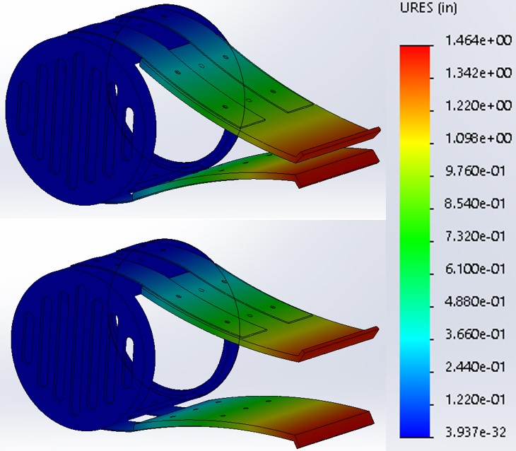
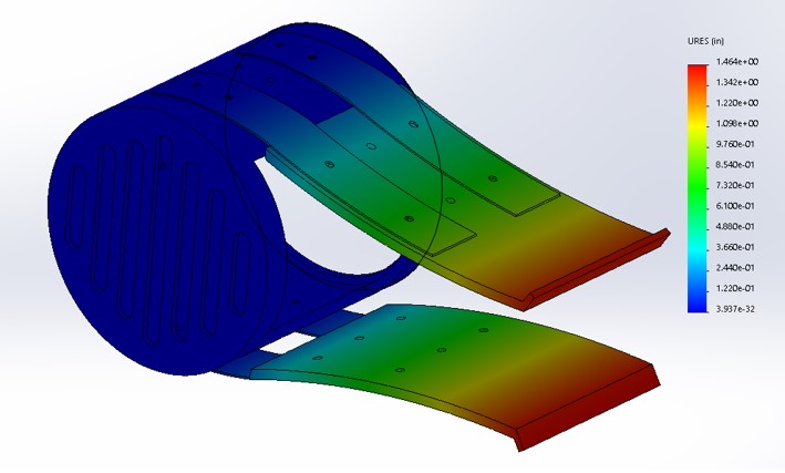
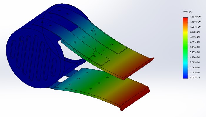
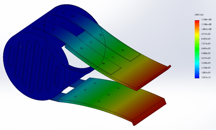
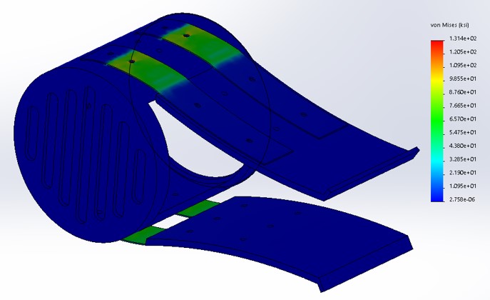
The device was analyzed and tested by using both virtual and physical prototyping. The virtual prototyping was accomplished by using SolidWorks Simulation. When testing the sampling device using virtual simulations, the main concern was whether the endplates would deflect 3 inches while having the actuation force remain reasonable for an astronaut. Therefore, the purpose of the analysis for this project was to (1) check that the device was able to properly deflect, (2) check that could still maintain that deflection at extreme temperatures, and (3) check if the actuation would still be possible after dropping. First, the proper deflection criteria were tested by using SolidWorks Simulation and the finite element analysis included its static study feature. The simulation was done by applying a force to the endplates until a displacement of 1.5 inches was achieved by each endplate.
The results of the virtual testing showed that a force of 6.74 pounds was needed to achieve 3.38 inches of deflection. Along with the deflection values, the stress results were found to be around 65.7 ksi which is under the yield strength needed for the device to fail. In addition to the force requirement, the thermal effects of the lunar surface were applied to see the effects of the highest and lowest temperatures on the moon. The temperatures used in the thermal analysis were 127°C and -173°C which were the temperatures found to be the high and low end of the lunar surface. When testing the device using the same force of 6.74 pounds with 127°C, the deflection was found to have decreased to 2.924 inches. Similarly, at -173°C, the deflection was found to have decreased to 3.046 inches. From the results, it can be seen that more actuation force is needed to achieve the same amount of deflection without these extreme temperatures. Finally, when doing a drop test study for the device at a height of 8 feet and using the moon’s gravity, the results show that there is no noticeable displacement and the maximum stress the device faces is 38.5 ksi.
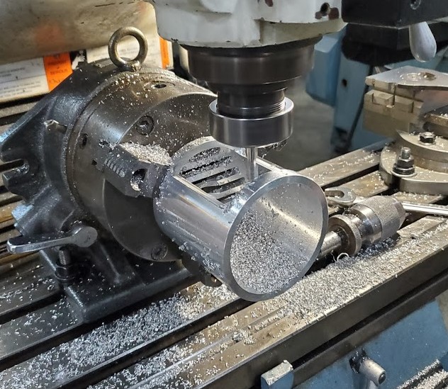
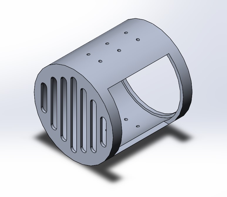
Manufacturing
The manufacturing process was made easier through the use of simple geometries and loose but thorough tolerancing. The housing was made using the vertical mill and lathe, the end plates with a wire EDM and mill, and the side guards with a wire EDM. The final design had a 3D printed cup and a premade handle due to time constraints and cost savings. Finally, the parts were connected either through riveting or welding.