Centrifugal Pump Impeller
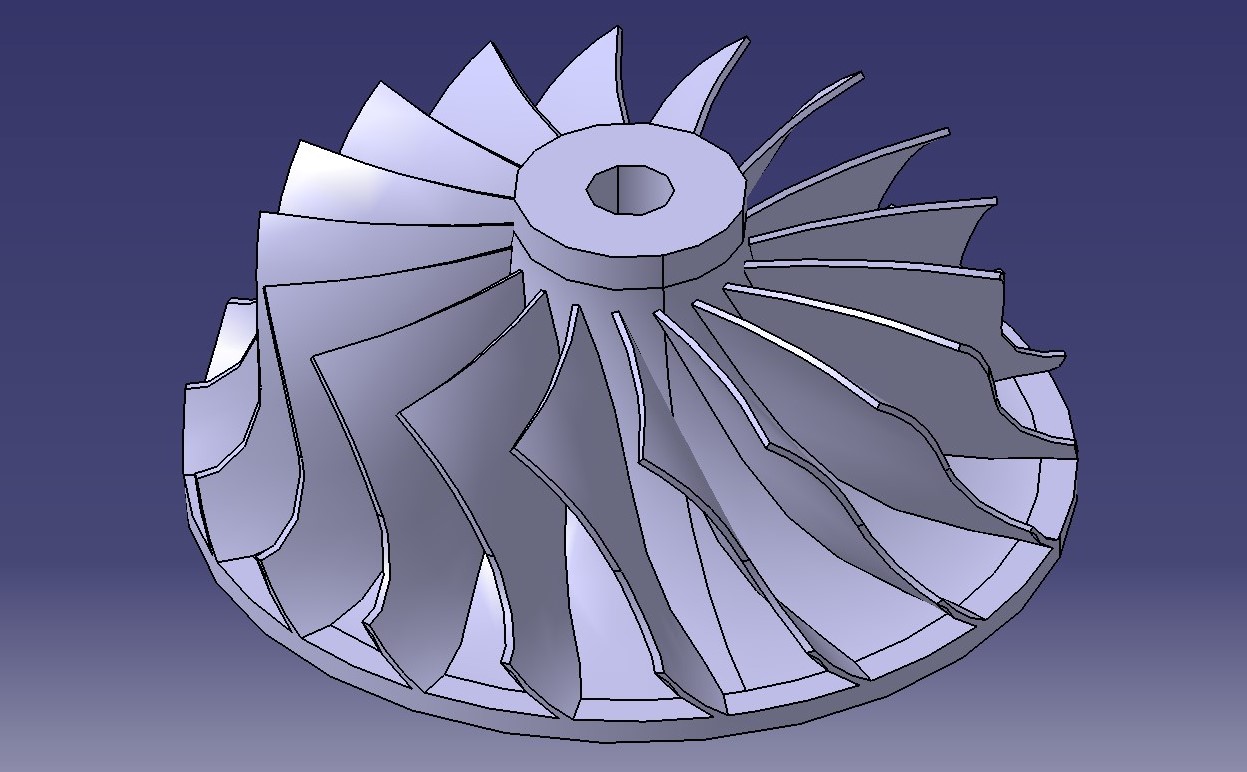
Semi-open centrifugal pump impeller design
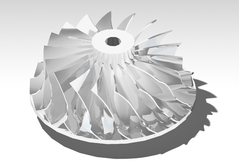
A centrifugal pump converts rotational energy into hydrodynamic energy through fluid flow. The centrifugal pump begins with rotational energy from a motor that then moves fluid into the pump casing. The fluid then enters the impeller blades and is sent out tangentially and radially back outside the casing. At this point, the fluid has gained velocity which is then converted into pressure energy/head. This design focuses on the impeller in which there are three different types: open, semi-open, and closed. Open impellers feature free vanes and have no discs enclosing them, semi-open impellers have one side of the vanes covered by a shroud, and closed impellers have vanes between two discs. For this design, a semi-open impeller design was modeled in CATIA V5.
Design Process
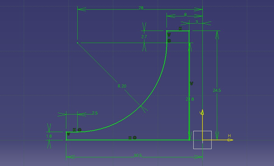
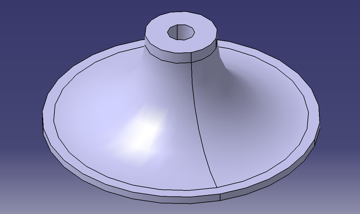
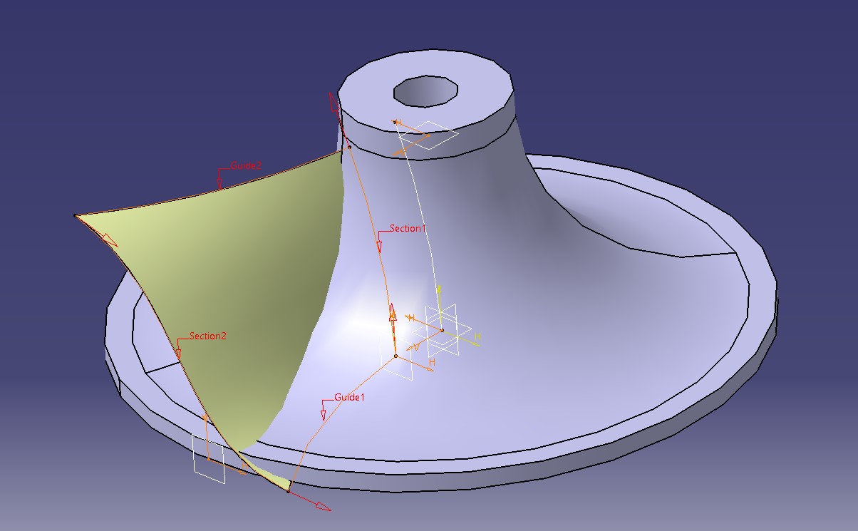
The first thing that was sketched for this impeller was the shaft or the eye of the impeller. This would serve as the base which the vanes would be placed around. The sketch was done in a way that it would be rotated around the z-axis. Afterwards, a vane was modeled by using multi-section surfacing and using four splines drawn in the x-y and z-x planes. Then, a circular pattern was made to duplicate the vane around the z-axis. Finally, excess material was cut out using the groove tool to complete the model.