Saturn V Bolted Nozzle Flange
Finite-element model of the Saturn V nozzle flange assembly
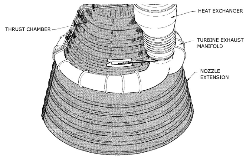
The Saturn V was a rocket used by NASA from 1967 to 1973 and it still holds the title as the most powerful rocket ever operated. The first stage of the Saturn V consisted of five F-1 engines which each have a thrust to weight ratio of 94:1 only beaten by the NK-33 and Merlin 1D rocket engines. In this project, the bolted flange joint of the F-1 engine nozzle was analyzed using a finite element model in ANSYS. The bolted flange joint connects the mid nozzle to the lower nozzle. The pressure and thermal strain due to the exhaust gas will be taken into account when looking at the deflection, strain, and the gap that may occur between the mid and lower flange.
Geometry & Load Steps
The F1 engine nozzle geometry was simplified to a cone in this analysis to reduce the complexity while still giving results on the same order of magnitude. In addition, since the nozzle geometry is symmetric around the z axis, the model was also reduced to a 0.9° section of the full geometry. This reduces the computing power required since only half a bolt is modeled rather than 200 bolts. Finally, the materials assigned to the flange parts are 300 series stainless steel for the nozzle walls and A-286 steel for the bolts and nuts.
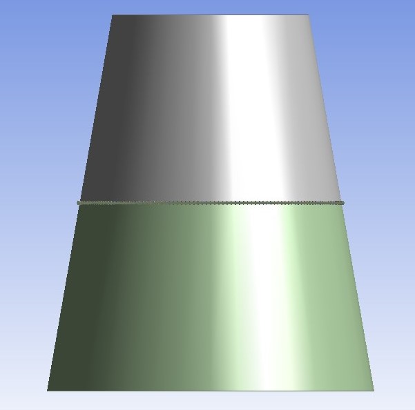
View of full nozzle
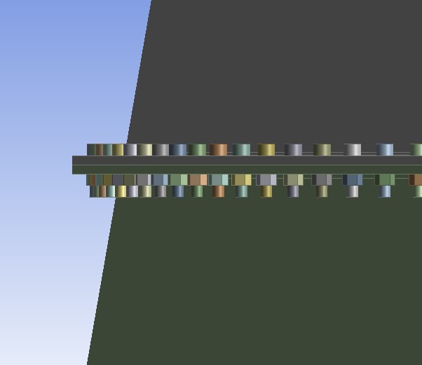
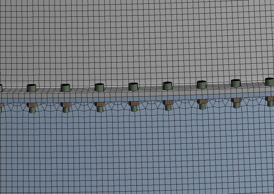
Closeup of flange joint
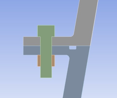
Section view through bolt
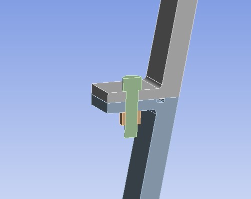
Reduced nozzle flange model
The load steps of this analysis begin with a bolt preload that comes from the tightening of the bolt which adds stress to the model. Secondly, the pressure and forces that cause seperation of the two flanges. The final load step is where the thermal condition is applied to the model. These load steps are applied by using tabular data on ANSYS. The bolt preload for the first load step was calculated as 4640 lbf or 50% of the breaking strength (9280 lbf). However, since we are using half a bolt the value has to be halved once again so the amount that was given to ANSYS was 2320 lbf. The second load stage includes the pressure due to the propellant which varies in the Z axis. The pressure at the top of the nozzle was set as 47.72 psi and 12.17 psi at the bottom. Additionally, a regenerative force is applied that seperates the two flanges and this is set at 1000 lbf at each flange face. For the first two load steps the temperature will be set at 70°F and then raised to 700°F at the final load step. After all these load steps were applied, contacts were made between the parts with the flange faces being frictionless to allow them to slide against each other.
Results
Deformation - bolt preload
Deformation - pressure
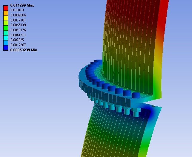
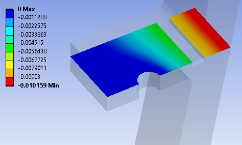
Deformation - thermal
Deformation thermal - bottom nozzle
The deformations seen above are scaled by a degree of 10. Through the first two load steps there seems to be a very small amount of deformation on the flange joint and nozzle wall. The first load step has a max deformation of 0.0014 inches and the second load step had a max deformation of 0.0113 inches. However, during the thermal load step, the ends of the wall of the nozzle is affected significantly as it expands by about 1.1 inches.
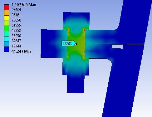
von-Mises after all load steps
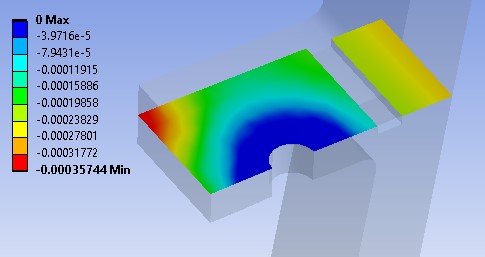
Gapping - bolt preload
Gapping - pressure

Gapping - thermal
The stress seen in the middle of the bolt is around 60ksi when using the probe tool on the contour. This can be checked by hand calculations by dividing the bolt preload force (2320 lbf) with the bolt area (.038 in^2). This calculation gives us a value of 61 ksi which is about the same. Comparing this value to the properties of A-286 steel show that it is well under its capability of 140ksi. The same can be said for the 300 series stainless steel walls after finding the hoop stress which comes to be just under 7ksi. The capability of the 300 series stainless steel is found to be more than 15ksi. Finally, the gapping between the surfaces where the flanges meet was another factor that had to be taken into account. The first load step shows no significant gapping which makes sense since there is only the bolt preload. The second load step shows 0.005 inch gapping at the area of interest which is the line along the sealing agent hole. The final load step shows no significant change as the area of interest still shows 0.005 inch gapping. If this gapping needed to be decreased the use of a thicker flange or even increasing the bolt preload would do so.
Error Analysis
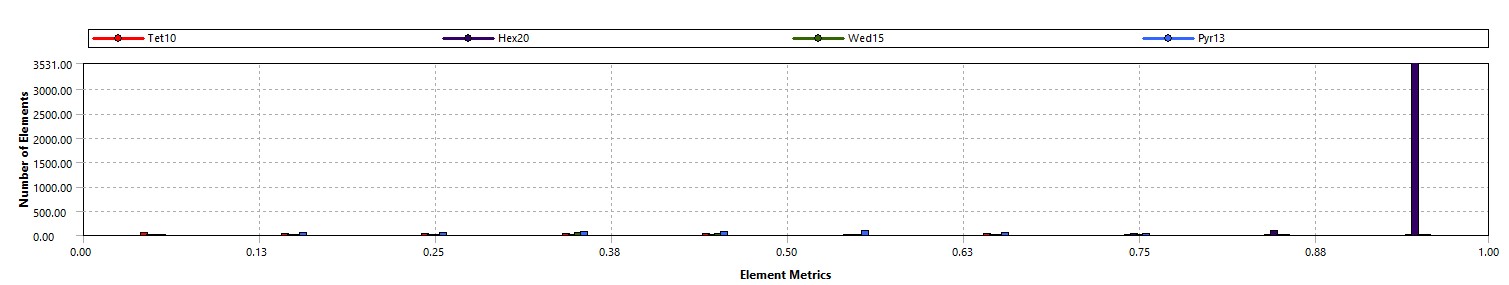
Mesh orthogonal quality
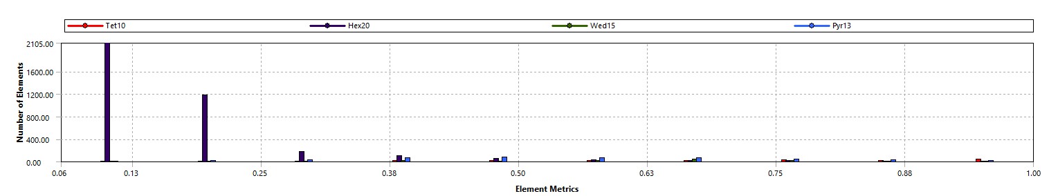
Mesh skewness
Average orthogonal quality and skewness of 0.89 and 0.22, respectively. A perfect mesh would have values of 1 for orthogonal quality and 0 for skewness meaning that there is some inaccuracies in this model. Also, the mesh that was made could also have been finer but due to limitations with the academic version (32000 nodes/elements). The geometry of the mesh was also a first-order approximation as it was modeled as a cone while the actual Saturn V nozzle had some more complexity.